NSX-T 3.1.1 – How to configure OSPF on Tier-0 Gateway
The wait has been long, but finally OSPFv2 can be configured on a Tier-0 Gateway. Until now only BGP or static routes were possible to route between the logical and (legacy) physical networks.
Table of Contents
How to configure it?
Upgrade to NSX-T 3.1.1
As OSPFv2 is only supported as from NSX-T 3.1.1, an upgrade is required. I will not explain the upgrade procedure. Upgrading NSX-T is well described in the official VMware documentation.
Configure OSPFv2
Physical router
In my lab environment I’m using a VyOS router. Underneath there is a part of my router configuration, before adding OSPFv2.
vyos@vyos:~$ show config
interfaces {
    ethernet eth0 {
        address 10.0.2.115/24
        hw-id 00:50:56:99:8d:18
    }
    ethernet eth1 {
        hw-id 00:50:56:99:5e:78
        vif 666 {
            address 10.0.144.1/30
        }
    }
    loopback lo {
        address 172.16.25.1/32
    }
}
protocols {
    bgp 65001 {
        address-family {
            ipv4-unicast {
                redistribute {
                    connected {
                    }
                }
            }
        }
        neighbor 10.0.144.2 {
            remote-as 65002
        }
    }
}
Three interfaces are configured:
- Eth0 is an interface in my physical network
- Eth1.666 is the interface which is configured to connect my router towards the Tier-0 Gateway. In my example I choose for a /30 subnet on VLAN 666.
- lo is a loopback address to simulate another subnet.
Routing protocol BGP is configured but disabled . I only advertise the connected subnets into BGP.
To add OSPFv2 as routing protocol, I add the following config. Be aware that the configuration can be different when using other vendors. More configuration is also possible and recommended when in a production environment.
protocols {
    ospf {
        area 0 {
            network 10.0.2.0/24
            network 10.0.144.0/30
            network 172.16.25.1/32
        }
    }
}
Having two routing protocols configured, is not an issue. I will come back on what the effect on the routing table is.
NSX-T Manager UI
Configuring OSPFv2 can be done via the NSX-T Manager UI. Steps are quite similar to these of setting up BGP. Let’s go over them.
Requirements which are not covered in this blog:
- A configured Edge Cluster (with edges in overlay and VLAN backed TZ)
- A configured Tier-0 Gateway
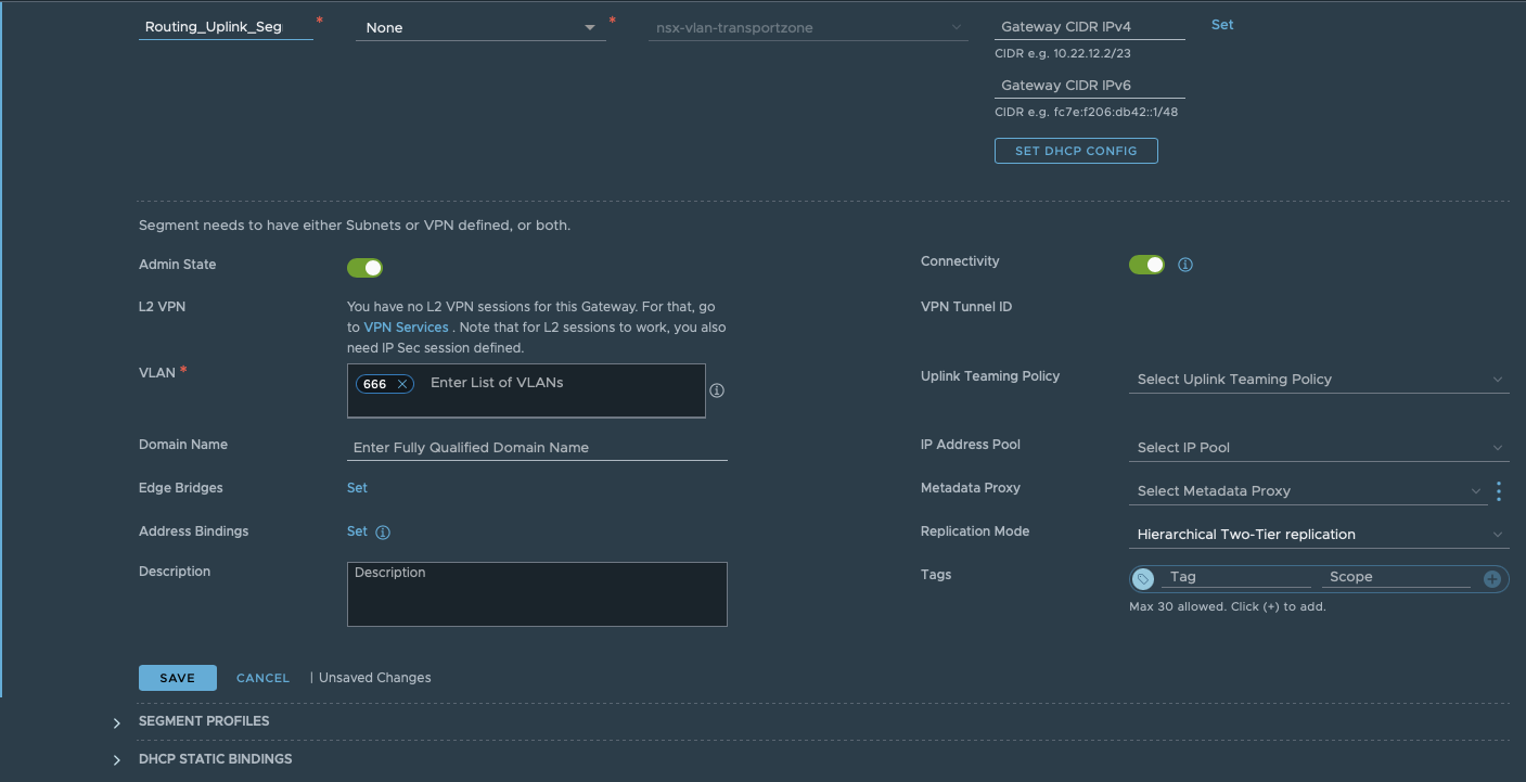
Step 1: Create an uplink segment in the correct VLAN. This segment will be used link between the T0 and the physical router.
As mentioned earlier, I’m using VLAN 666. Be sure this VLAN is also configured on all necessary switches/VDS port groups or trunked NSX-T segments, depending on your design.
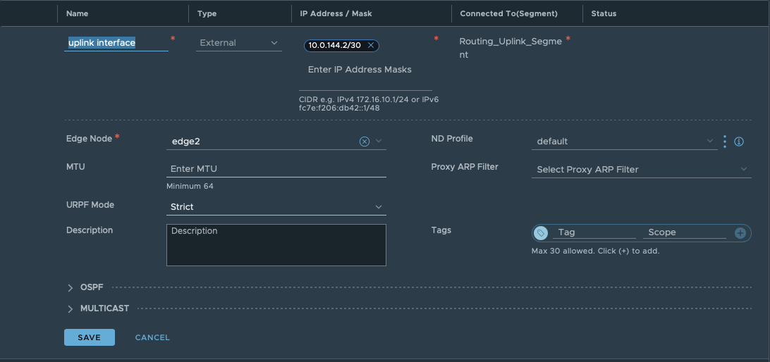
Step2: Create an interface on the T0 Gateway. Specify a name, subnet and connect it to the segment created in Step 1. Aswell choose the edge node where the interface should be created.
Underneath the OSPF tab, you can see that this interface is still disabled for OSPF. It will be enabled in the next step.
Click save and close.
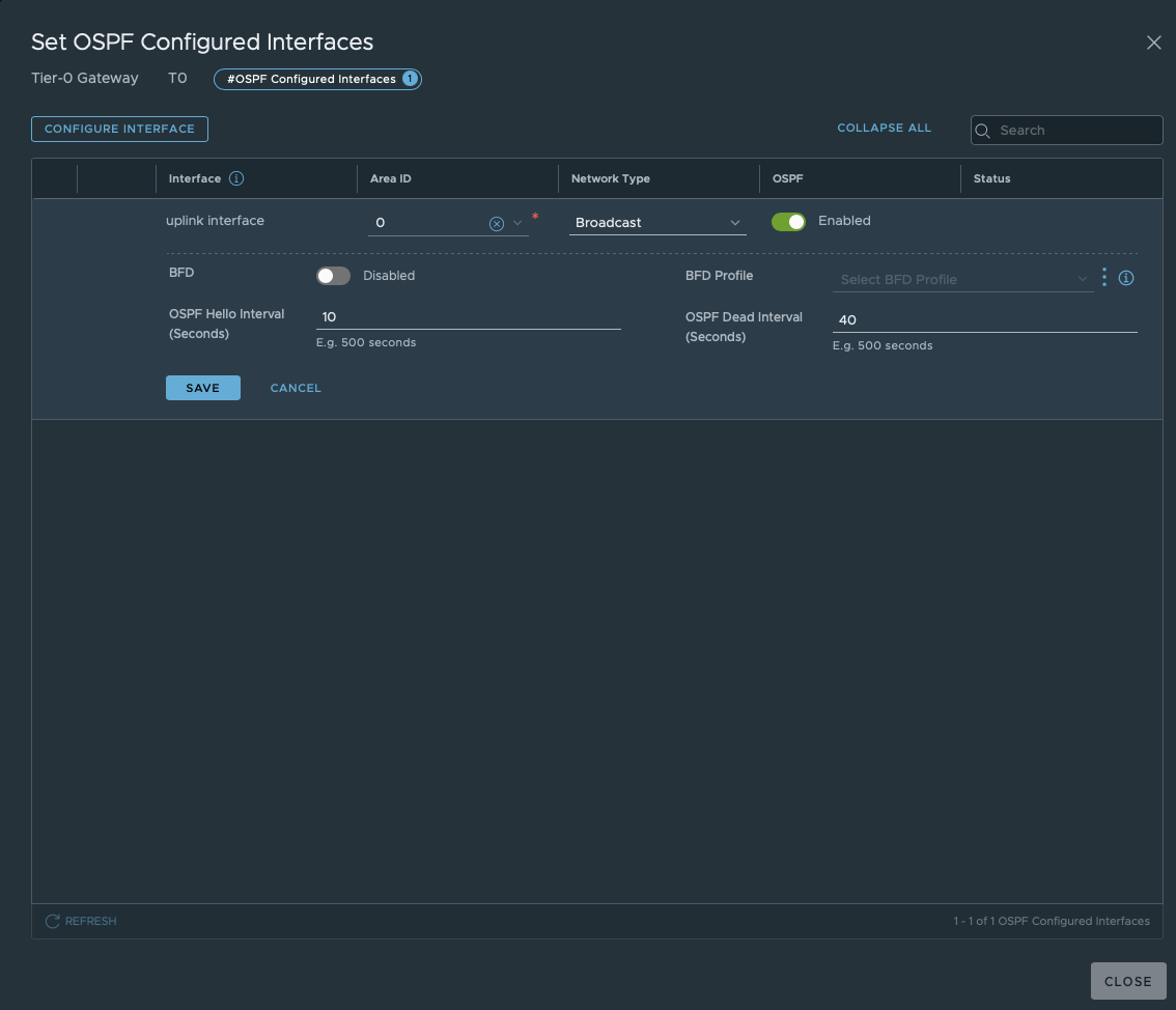
Step 3: Open the OSPF tab. Enable OSPF and define an area ID. The ID has to be the same as configured on the physical router.
Only after defining an area ID, continue by configuring “OSPF Configured Interfaces”. Here you select the earlier created interface and OSPF area ID.
The field “Network Type” has two possibilities: Broadcast or P2P. Choose the right one depending on your OSPF configuration and design.
In short: P2P doesn’t hold DR elections, so it doesn’t work if more than two routers are configured on a subnet. P2P network types are intended to be used between 2 directly connected routers. The broadcast network type is the default for OSPF.
Again click save and close
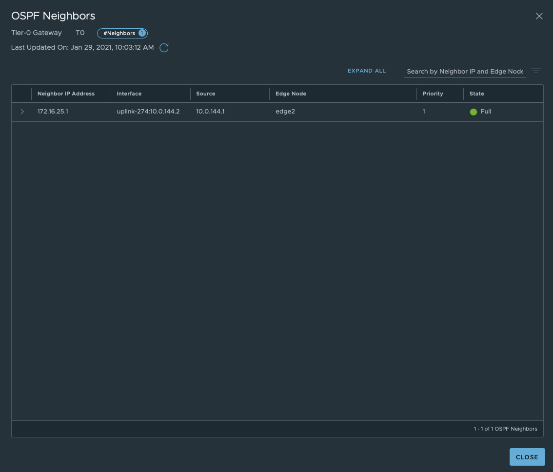
Step 4: Before advertising routes, check if OSPF has discovered its neighbour. In this situation he should discover your physical router.
When still in the OSPF tab, click “View” next to OSPF Neighbours. If you configured both sides correctly, you should see the neighbourship with the physical router.
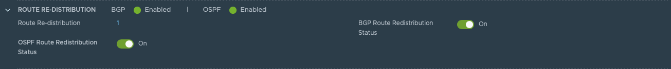
Step 5: Open the route re-distribution tab. Here you enable “OSPF Route Redistribution Status”
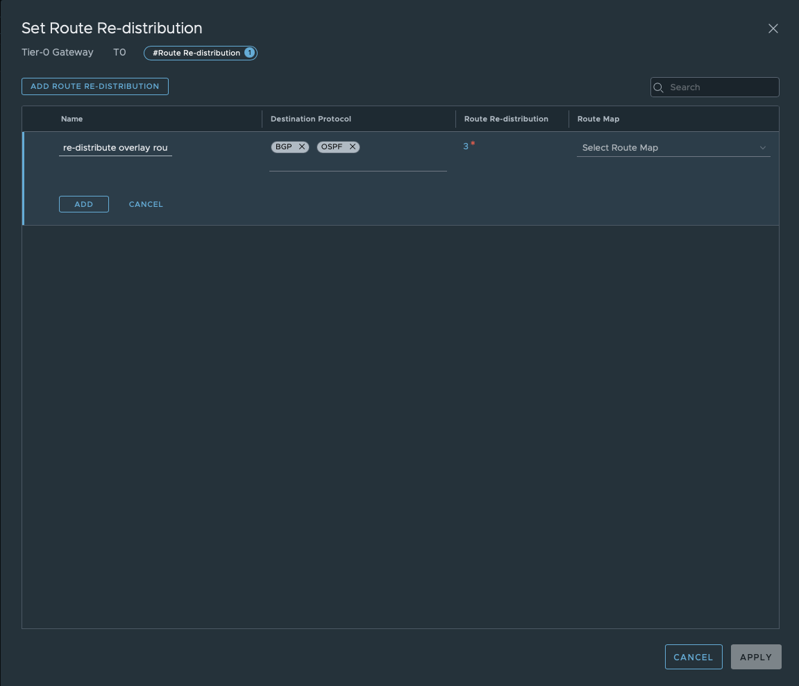
Set “Route Re-distribution” by clicking set. Fill in a name and choose the required Destination Protocol. In this case: choose OSPF.
In my lab I configured OSPF and BGP. For this reason I selected both protocols. This to show you what the impact is on the routing table. BGP is configured, but disabled for now.
Don’t forget to select the sources which needs to be advertised towards the physical router.
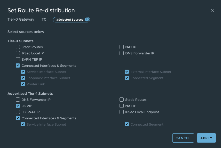
Save this configuration.
All configuration should be done by now. Let’s do some verification.
Verificate OSPFv2 routing
Tier-0 SR
- Login as admin into the edge node where you did the configuration for. (via SSH)
- Switch to the correct VRF by executing
vrf x. (x = number of T0-SR VRF) - Check the routing table by executing
get route
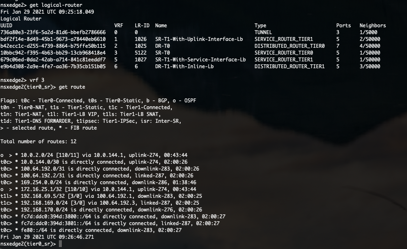
In this routing table you can see all routes this T0 has learned and via which protocol.
As you can see in the above screenshot, routes to 10.0.2.0/24 and 172.16.25.1/32 are learned via OSPF. Isn’t that what we have configured on the physical router? Not completely. Where is the OSPF route towards 10.0.144.0/30?
Because the directly connected route is more preferred, this OSPF route is not visible in the routing table.
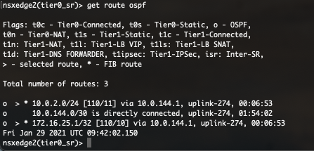
By executing get route ospf you can see all learned OSPF routes. In this table, the route is visible but not selected (>).
Physical router
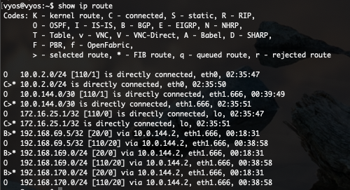
Besides checking the routing table on the Tier-0 Gateway, you can also verify the OSPFv2 on the physical router. Commands used in this chapter can vary depending on your vendor.
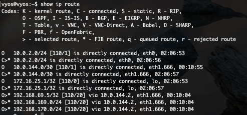
In above screenshot you see 6 routes learned via OSPF. But only 3 are selected. This for the same reason I’ve explained before. Directly connected routes are preferred.
Now my physical router knows how to route towards all overlay segments (192.168.x.x/24) and even the NSX-T load balanced VIP.
Both OSPFv2 and BGP configured, what now?
If both OSPFv2 and BGP are configured, both the Tier-0 Gateway and physical routes have multiple ways to route to the advertised subnets/segments. Which will be preferred?
Routes will be preferred by looking at its Administrative distance. Routes with the lowest AD will be preferred.
Definition
Administrative distance is the feature that routers use in order to select the best path when there are two or more different routes to the same destination from two different routing protocols. Administrative distance defines the reliability of a routing protocol. Each routing protocol is prioritized in order of most to least reliable (believable) with the help of an administrative distance value. (ref.: https://www.cisco.com/c/en/us/support/docs/ip/border-gateway-protocol-bgp/15986-admin-distance.html)
AD Values
Each routing protocol has an Administrative distance. These values can depend from vendor. The AD value is only local and can be different for each router. Manually configuration is possible as well.
Broadly known values are:
| Directly connected | 0 |
| Static route | 1 |
| EIGRP summary | 5 |
| External BGP | 20 |
| EIGRP | 90 |
| IGRP | 100 |
| OSPF | 110 |
| IS-IS | 115 |
| RIP | 120 |
| ODR | 160 |
| External EIGRP | 170 |
| Internal BGP | 200 |
| Unknown | 255 |
Let’s check the routing tables again after enabling BGP.
Tier-0 SR
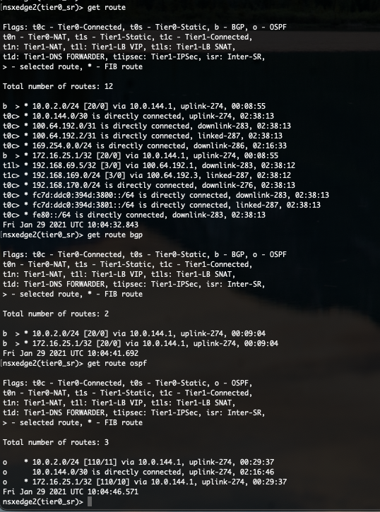
As you can see in the above protocol specific routing tables, routes has been learned via OSPF and BGP. But we can see that the AD of BGP is only 20 and the AD of OSPF is set at 110. The AD value is put between square brackets [AD/Metric] in the routing table.
Because 20 is lower than 110, the BGP route is preferred. The preferred routes are tagged with “>”.
Physical router
The VyOS router shows similar behaviour. BGP is preferred over OSPF because of the same reason.
End of this post
Thanks for reading this blog. I hope you learned some new interesting things.
If you have some questions or if you see some mistakes in one of my blog posts, don’t hesitate to contact me.