Part 3: One-Arm Topology – The Impact Of The Load Balancing Service on your NSX-T Data Center Data Flow
Table of Contents
Impact of the One-Arm topology on your NSX-T data flow
Now that you know the different supported topologies and the exact impact on the data flow for the inline topology, let’s continue with the exact impact on the data flow for the one-arm topology.
Have you missed the first two parts? Check them out:
- The Impact Of The Load Balancing Service on your NSX-T Data Center Data Flow Part1
- The Impact Of The Load Balancing Service on your NSX-T Data Center Data Flow Part 2: Inline Topology
Lab Topology
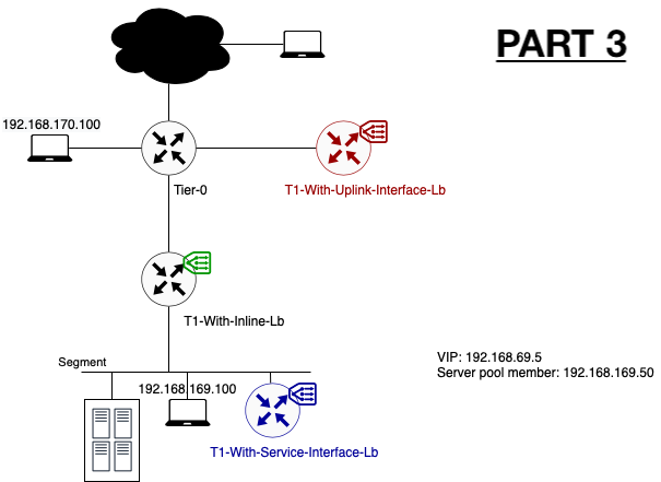
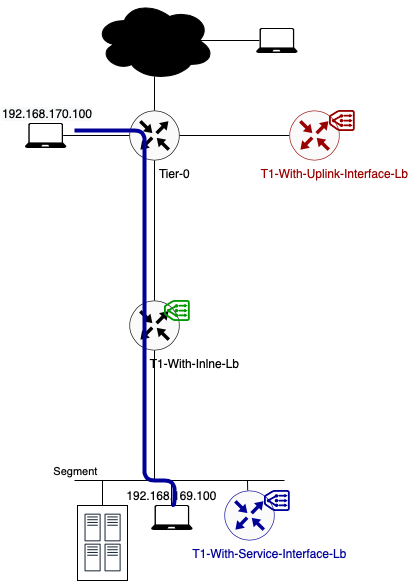
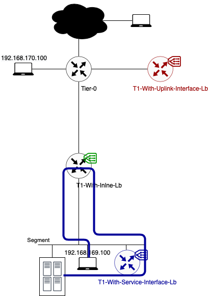
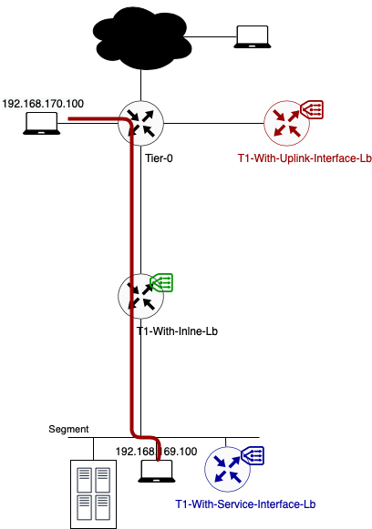
To explain the impact on the traffic flow, I will use the following basic setup. Different colours are showing the different topologies I will explained.
Note: Because of the limited lab size, the edge and compute nodes are running in a fully collapsed cluster. For more information, please reach out to me.
Note 2: To have a more optimal lab topology, I removed the load balancer from the T1-With-Inline-Lb. The reason for this is to avoid additional hops. Check part 2 to have a look on the impact of an inline load balancer.
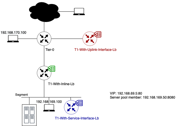
The server member behind the Virtual server IP is running a simple webserver on port 8080. The virtual server itself is listening on port 80.

One-Arm Load Balancer
The data path when using a one-arm load balancer topology is different than with an inline load balancer. With a one-arm load balancer not all traffic is passing through the load balancer. Only traffic destined for a load balancer service is being redirected to it. Other traffic is following the default NSX-T routing flow.
As mentioned in part 1 there are two configuration methods. We will take a look at both to define the impact on the data flow.
VIP Placement
When using an one-arm load balancer, the VIP can be placed in the following subnets:
- T1 Downlink Segment -> When using T1 service interface
- A new dedicated loopback subnet (but manual route advertisement needed) -> When using T1 service/uplink interface
Using T1 Service Interface
The newly created (standalone) Tier-1 Gateway/load balancer is connected to the same segment where it needs to load balance for. What’s the impact on the data flow? Let’s check it out.
Data path example 1: Traffic from 192.168.170.100 to VIP 192.168.69.5 (TCP:80)
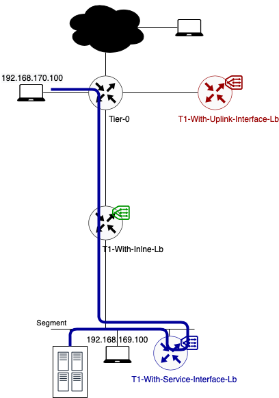
In this example, client and server are not located on the same segment.
- As you can see in the above diagram traffic flows from the source to its default gateway. The default gateway for segment 192.168.170.0/24 is located on the directly connected Tier-0 Gateway.
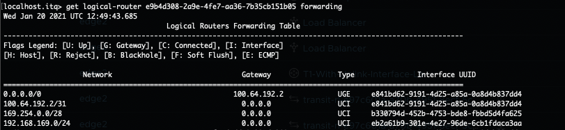
- This Tier-0 gateway knows where to route the traffic to (after checking its routing table). In this case the next hop is the Tier-1 Gateway called “T1-With-Inline-Lb. Because this T1 has no centralised services deployed, no T1 SR component exists. Traffic is forwarded to T1 DR component directly.
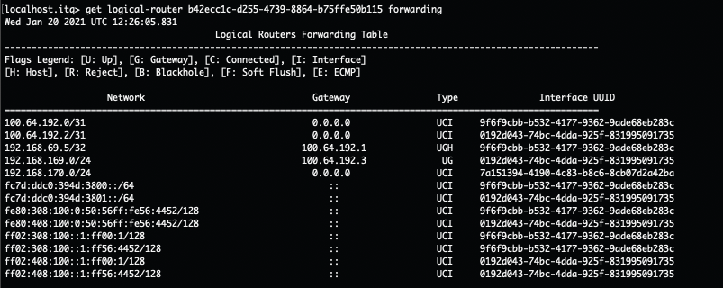
- The T1 DR checks its routing table and knows how to route traffic to this VIP. According to the routing table, the next hop is the service interface IP on the T1-With-Service-Interface-Lb where the load balancer is hosted. This IP (192.168.169.2) is part of the directly connected Server_Segment.
- To get to 192.168.169.2, traffic is encapsulated and tunnelled from the source ESXi host to the Edge node where the T1-With-Service-Interface-LB SR component is hosted. There it gets forwarded to the load balancer.
- After the load balancer did his magic (my way of saying that I will not go deeper into the load balancer process), the traffic knows what his final destination is. In this case VIP 192.168.69.5:80 is redirecting the traffic to my only server pool with webserver 192.168.169.50:8080. The traffic is sent back to the T1 SR component (T1-With-Service-Interface-Lb).
- As the load balanced server IP is in the same subnet as the Service IP, no routing is needed. The routing process is over.
- The Edge host switch will first check its ARP Table to make the conversion between VM IP and VM MAC. Secondly the MAC address table is checked. Based on VM MAC, this table knows on which ESXi host (TEP IP) the final destination (webserver VM) is located.
- Traffic is encapsulated and tunnelled from the Edge node to the destination ESXi host.
- The receiving host decapsulates the traffic and sends it to the webserver 192.168.169.50.
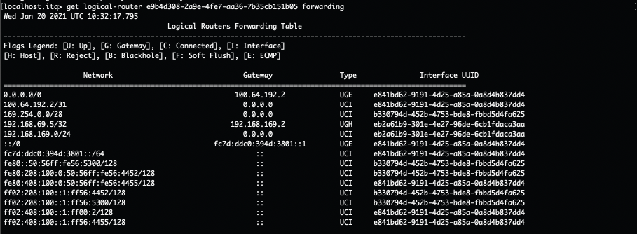
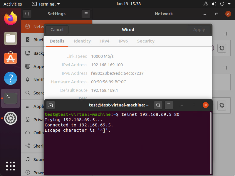
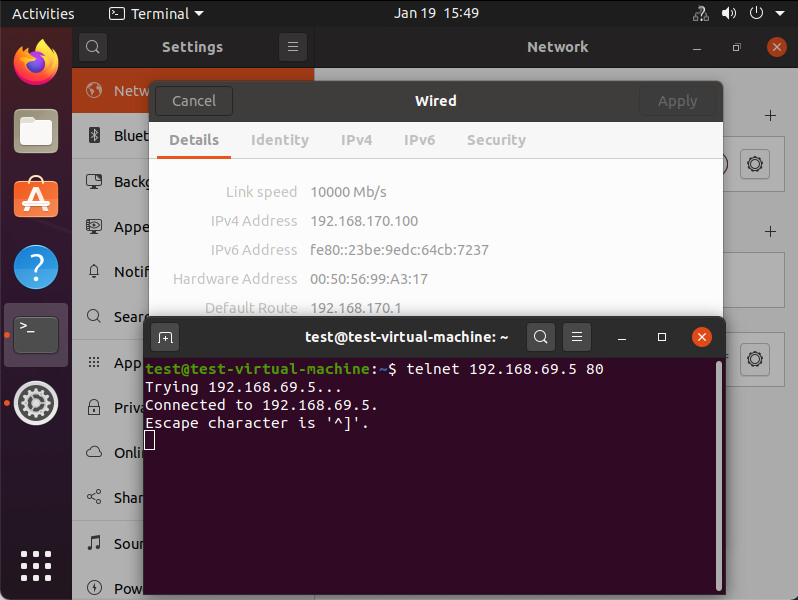
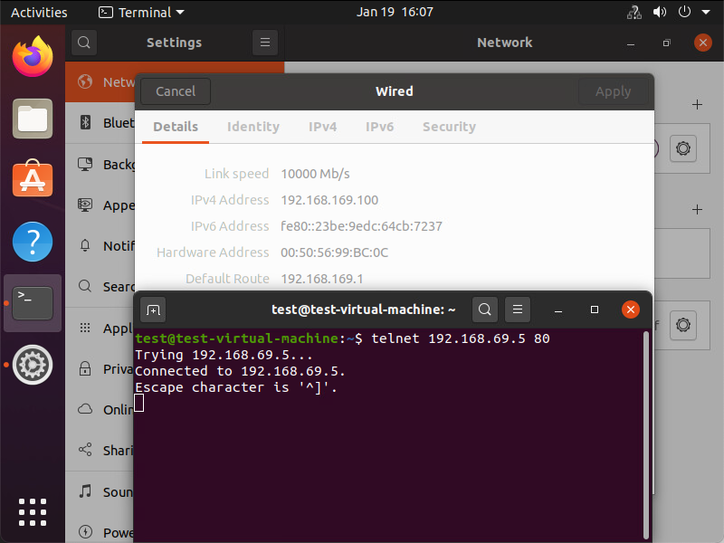
Underneath you can see that the traffic is reaching its final destination. In this screenshot I’m using telnet to check if port 80 on the VIP is opened from the source VM.

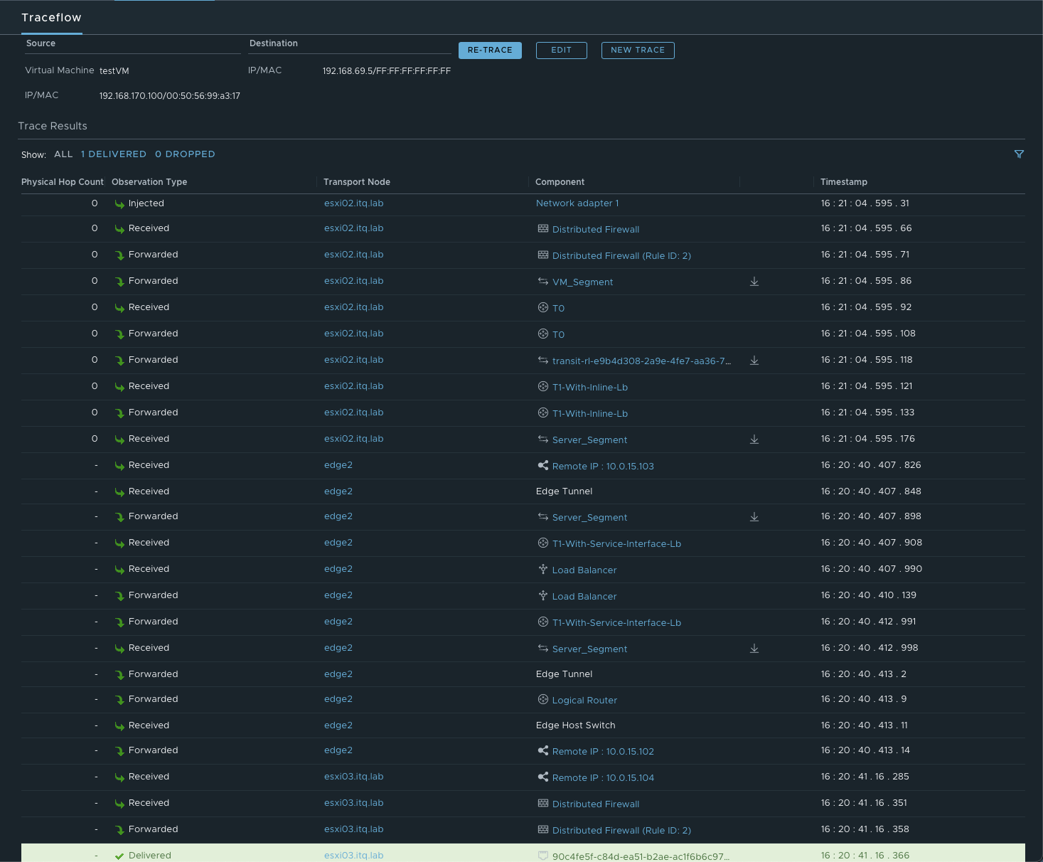
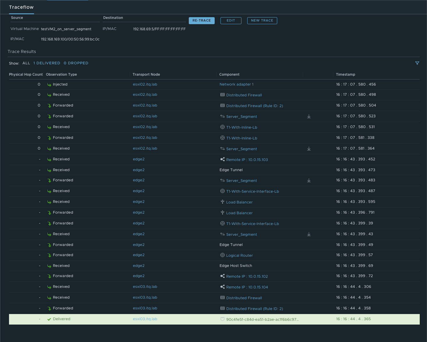
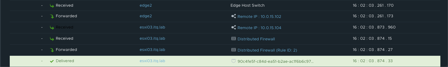
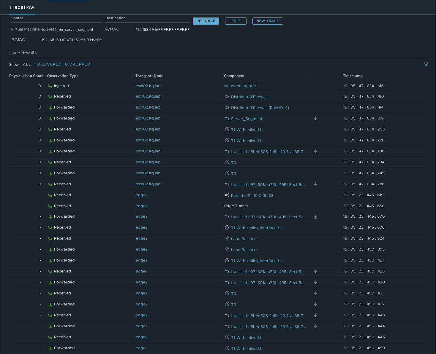
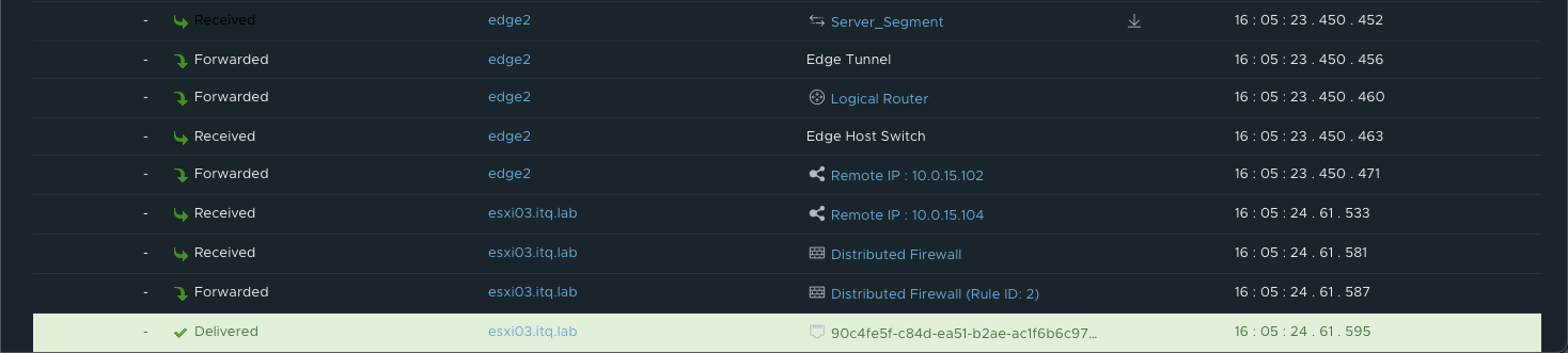
More details about the exact path can be seen during a trace flow within the NSX-T Manager.
Data path example 2: Traffic from 192.168.170.100 to 192.168.169.100 (ICMP)
During this second example, I’m sending traffic which is not destined for a VIP on the load balancer. How does the traffic flows in this case?
As you can see in the above diagram, traffic is not passing through any load balancer. When using a one-arm load balancer, only VIP traffic is being routed to the load balancer service.
This means that, in this example, traffic is using the most optimal way of routing. It takes no unnecessary hops. All routing can be done in a distributed way.
- Because source and destination IP are on different subnets, the traffic flows from the source to its default gateway. The default gateway for segment 192.168.170.0/24 is located on the directly connected Tier-0 Gateway.
- This Tier-0 gateway knows where to route the traffic to (after checking its routing table). In this case the next hop is the Tier-1 Gateway called “T1-With-Inline-Lb. Because this T1 has no centralised services deployed, no T1 SR component exists. Traffic is forwarded to T1 DR component directly. This routing takes place in a distributed way. Traffic is not leaving the source ESXi host.
- Once the traffic arrives on the T1 DR component, the routing process is over. From here on traffic is handled as Layer 2 (switching) as the Server_Segment is directly connected to this distributed router.
- The host switch will first check its ARP Table to make the conversion between VM IP and VM MAC. Secondly the MAC address table is checked. Based on VM MAC, this table knows on which ESXi host (TEP IP) the final destination (webserver VM) is located.
- In this example, source and destination VM are located on the same ESXi hosts. Traffic is forwarded directly to the webserver. In case both VMs are located on different ESXi hosts, the traffic is encapsulated and tunnelled from the source ESXi host to the destination ESXi host. The receiving host decapsulates the traffic and sends it to the webserver 192.168.169.50.
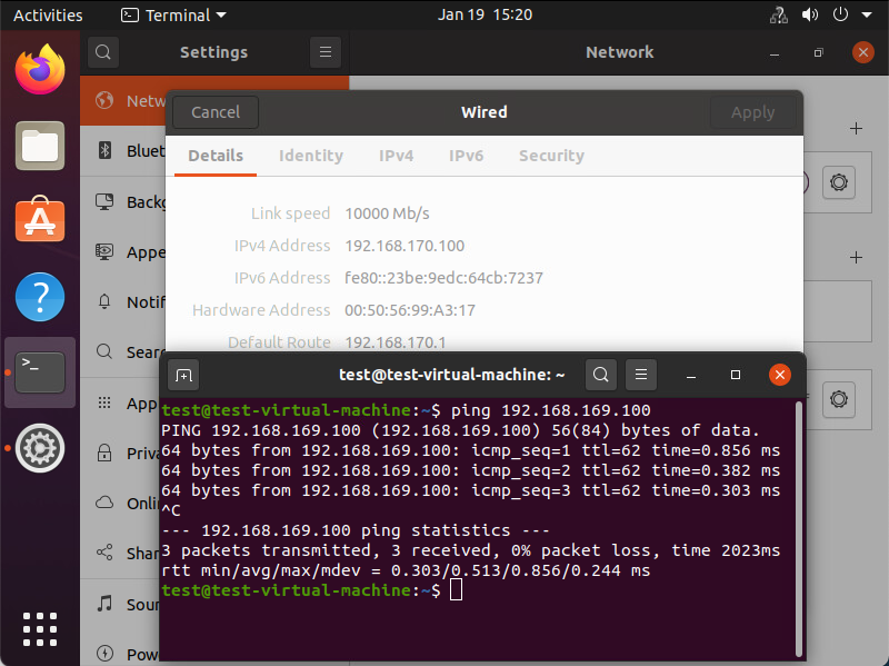
Underneath you can see that the traffic is reaching its final destination. In this screenshot I’m sending ICMP packets to check connectivity towards the destination VM.
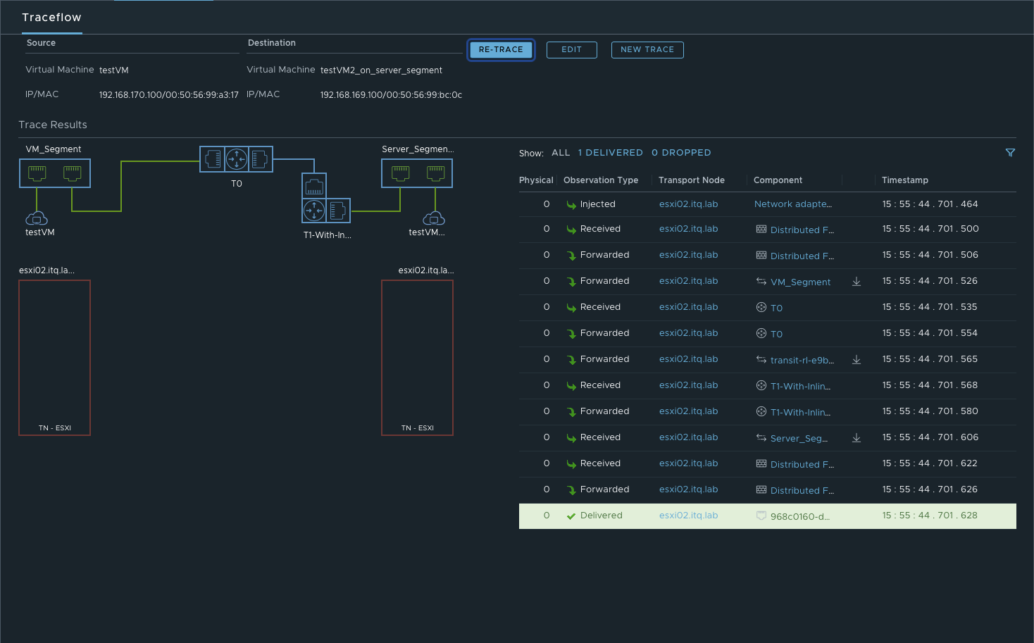
More details about the exact path can be seen during a trace flow within the NSX-T Manager.
Data path example 3: Traffic from 192.168.169.100 to VIP 192.168.69.5 (TCP:80)
- Because source and destination IP (192.168.69.5) are on different subnets, the traffic flows from the source to its default gateway. The default gateway for segment 192.168.169.0/24 is located on the directly connected Tier-1 Gateway.
- This Tier-1 gateway knows where to route the traffic to (after checking its routing table). According to the routing table, the next hop is the service interface IP on the T1-With-Service-Interface-Lb where the load balancer is hosted. This IP (192.168.169.2) is part of the directly connected Server_Segment.
- To get to 192.168.169.2, traffic is encapsulated and tunnelled from the source ESXi host to the Edge node where the T1-With-Service-Interface-LB SR component is hosted. There it gets forwarded to the load balancer.
- After the load balancer did his magic (my way of saying that I will not go deeper into the load balancer process), the traffic knows what his final destination is. In this case VIP 192.168.69.5:80 is redirecting the traffic to my only server pool with webserver 192.168.169.50:8080. The traffic is sent back to the T1 SR component (T1-With-Service-Interface-Lb).
- As the load balanced server IP is in the same subnet as the Service IP, no routing is needed. The routing process is over.
- The Edge host switch will first check its ARP Table to make the conversion between VM IP and VM MAC. Secondly the MAC address table is checked. Based on VM MAC, this table knows on which ESXi host (TEP IP) the final destination (webserver VM) is located.
- Traffic is encapsulated and tunnelled from the Edge node to the destination ESXi host.
- The receiving host decapsulates the traffic and sends it to the webserver 192.168.169.50.
Underneath you can see that the traffic is reaching its final destination. In this screenshot I’m using telnet to check if port 80 on the VIP is opened from the source VM.
More details about the exact path can be seen during a trace flow within the NSX-T Manager.
Using T1 Uplink Interface
Data path example 1: Traffic from 192.168.170.100 to VIP 192.168.69.5 (TCP:80)
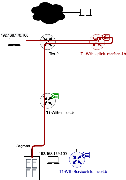
In this example, client and server are not located on the same segment.
- As you can see in the above diagram traffic flows from the source to its default gateway. The default gateway for segment 192.168.170.0/24 is located on the directly connected Tier-0 Gateway.
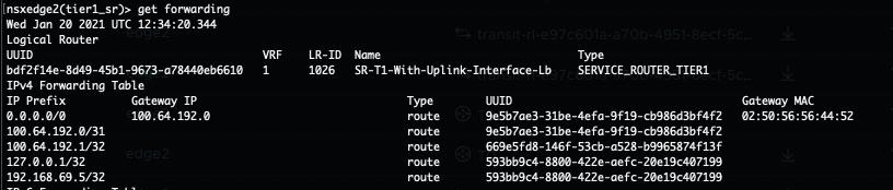
- This Tier-0 gateway knows where to route the traffic to (after checking its routing table). In this case the next hop is the Tier-1 Gateway called “T1-With-Uplink-Interface-Lb where the load balancer is hosted (100.64.192.1).
- To get to 100.64.192.1, traffic is encapsulated and tunnelled from the source ESXi host to the Edge node where the T1-With-Uplink-Interface-LB SR component is hosted. There it gets forwarded to the load balancer.
- After the load balancer did his magic (my way of saying that I will not go deeper into the load balancer process), the traffic knows what his final destination is. In this case VIP 192.168.69.5:80 is redirecting the traffic to my only server pool with webserver 192.168.169.50:8080. The traffic is sent back to the T1 SR component (T1-With-Uplink-Interface-Lb).
- This T1 SR component knows where to route the traffic to (after checking its routing table). In this case the next hop is back to the T0 Gateway (100.64.192.0). This routing happens locally on the Edge node.
- On its turn the T0 DR component knows where to route the traffic to (after checking its routing table). In this case the next hop is to the T1 Gateway called T1-With-Inline-lb. Again this routing happens locally on the Edge node.
- Once the traffic arrives on the T1-With-Inline-Lb, the routing process is over. From here on traffic is handled as Layer 2 (switching) as the Server_Segment is directly connected to this distributed router.
- The Edge host switch will first check its ARP Table to make the conversion between VM IP and VM MAC. Secondly the MAC address table is checked. Based on VM MAC, this table knows on which ESXi host (TEP IP) the final destination (webserver VM) is located.
- Traffic is encapsulated and tunnelled from the Edge node to the destination ESXi host.
- The receiving host decapsulates the traffic and sends it to the webserver 192.168.169.50.
Underneath you can see that the traffic is reaching its final destination. In this screenshot I’m using telnet to check if port 80 on the VIP is opened from the source VM.
More details about the exact path can be seen during a trace flow within the NSX-T Manager.

Data path example 2: Traffic from 192.168.170.100 to 192.168.169.100 (ICMP)
During this second example, I’m sending traffic which is not destined for a VIP on the load balancer. How does the traffic flows in this case? Let’s check it out.
When looking at the above diagram, this traffic flow is 100% similar to the one I’ve explained in the One-Arm load balancer using the Service Interface (example 2). Traffic is not passing through any load balancer. When using a one-arm load balancer, only VIP traffic is being routed to the load balancer service. For more information, please scroll up or click here to see example 2 of previous chapter.
More details about the exact path can be seen during a trace flow within the NSX-T Manager.

Data path example 3: Traffic from 192.168.169.100 to VIP 192.168.69.5 (TCP:80)

When looking at the above diagram, the traffic flow looks very similar to the one I’ve explained in the One-Arm load balancer using the Uplink Interface (example 1). The only difference is that the source traffic is not directly connected to the Tier-0 Gateway.
- Instead, traffic is being send to its default gateway which is located on T1-With-Inline-Lb.
- From there it follows the default route which leads to the Tier-0 Gateway. This is because the routing table on T1-With-Inline-Lb has no destination for the VIP. All the routing happens locally on the source ESXi host.
- Once it’s routed towards the T0, it follows the exact same steps as explained in he One-Arm load balancer using the Uplink Interface (example 1). You can continue reading there, from the second bullet point.
Underneath you can see that the traffic is reaching its final destination. In this screenshot I’m using telnet to check if port 80 on the VIP is opened from the source VM.
More details about the exact path can be seen during a trace flow within the NSX-T Manager.
End of this series
Thanks for reading this series. I hope you learned some new interesting things.
If you have some questions or if you see some mistakes in one of my blog posts, don’t hesitate to contact me.