Part 1 – The Impact Of The Load Balancing Service on your NSX-T Data Center Data Flow
About the installation and configuration of NSX-T Data Center and its features, you can find more than enough information in the official VMware documentation or other subject-specific blogs of NSX-T Experts. But what is now the impact of the load balancing service on your NSX-T Data Center environment? How does it affects the data flow?
With the above in mind, I assume when you start reading this post you have a certain level of networking, load balancing and NSX-T Data Center knowledge. If not, some things may be difficult to understand.
Everything which is mentioned here, has been tested in the ITQ home lab which is running NSX-T 3.1.
Table of Contents
Supported topologies
In this first chapter I will shortly summarise the different supported load balancing topologies. No in-depth explanation will be done.
Please remember that NSX-T Load balancers are only possible on a Tier-1 Gateway and that there is a 1:1 mapping between a load balancer and a specific Tier-1 gateway.
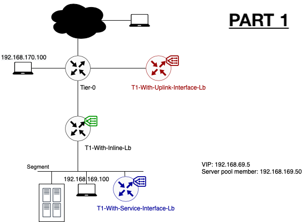
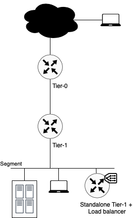
Inline Load Balancer
As the term it already says, the load balancer is being placed inline with the data flow. Meaning that the load balancer is placed in the data path between the client and the server. One of the drawbacks of placing the load balancer inline is that client and server may not be connected to the same Tier-1 Gateway.
SNAT is not required in this topology.
One Arm Load Balancer
Differently to the earlier (inline) topology, the load balancer is not being placed in the data path between the client and server. Traffic destined for the load balancer will be hair pinned out of the regular data path to the centrally placed load balancer and back.
In this topology it doesn’t matter where client and server are located. Client and server can be connected to the same segment or Tier-1 Gateway.
SNAT is required in this topology. By enabling SNAT the server response is always sent back to the load balancer. It’s the load balancer which forwards the response to the client.
The biggest advantage of a one arm load balancer is that not all traffic needs to pass through the load balancer. Non-load balanced traffic can just follow the original data path. More in-depth information on the impact is addressed in the upcoming posts of this series.
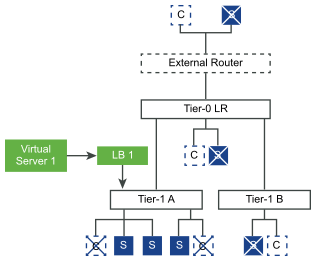
Using T1 Service Interface
Configuring a one arm load balancer can be done by using the Tier 1 Service Interface. The newly created (standalone) Tier-1 Gateway is connected to a segment directly via a service interface. The standalone Tier-1 interface gets an IP in the same segment where it needs to load balance for.
Note that for a standalone Tier-1 which performs load balancing functionalities there is a limitation of only ONE service interface per Tier-1 Gateway. The effect of this limitation is that for each load balanced segment, you will have to create a new Tier-1 Gateway and load balancer. This limitation can have a huge impact on your required resources. Take a look at the limits for NSX-T load balancing here.
To make this configuration work, please don’t forget to add the static route on the standalone Tier-1 Gateway. This ensures that load balanced traffic can leave the segment. More information about configuration can be found in the official VMware documentation.
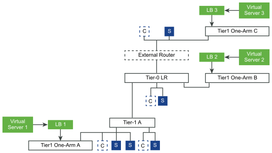
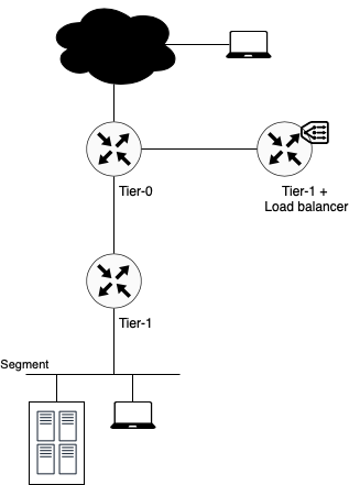
Using T1 Uplink Interface
Another way of configuring a one arm load balancer is via a Tier-1 Uplink Interface. Instead of connecting the load balancer to the segment itself, it is connected as a standalone Tier-1 Gateway to the existing Tier-0 Gateway in the environment. In this case two Tier-1 Gateways are connected to the Tier-0 Gateway. One where different segments are connected to and one which is dedicated for the load balancer.
By using this method, you can get rid of the limitation of having one Tier-1 Gateway and load balancer per segment.
Instead of creating a Tier-1 Service Interface and a static route, just link the Tier-1 gateway to the Tier-0 Gateway.
Up Next: The Impact Of The Load Balancing Service on your NSX-T Data Center Data Flow Part 2: Inline Topology
Now that we know the different supported topologies, it would be good to know what the exact impact is on the data flow itself. How much traffic is passing through the load balancer and how is traffic passing through the different NSX-T Data Center components. In the next blog I will demonstrate it for the Inline Load Balancer Topology.